Showing posts with label Modifications. Show all posts

August 15, 2011

DIY ADC to DVI converter

 A while back I was able to grab a 17 inch LCD Cinema Display from electronic surplus for 5$, while this sounds like an amazing deal, there was one extra issue that made this more fun than just being able to use it without some effort on my part.  Older Apple Cinema Displays use an ADC connector which while similar to the popular DVI, is only supported on a few older G4 towers and video cards.  Luckily I already have a working G4 mirror door with a graphics card that has the connector.  My original mod to fix the broken power supply prevents me from using the ADC connector due to lack of the extra 24v line, so with the help of my trusty heat gun, off went the connector for external use in this project to build an ADC to DVI adaptor.


First off I started looking for other people that had done this before.  While there is not a lot of information beyond a few others that have succeeded, there is a retail converter from Apple, so it is possible.

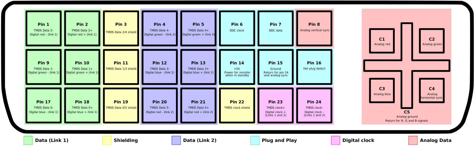
 The pinouts are quite simple to folow as ADC shares a lot in common with DVI as they are both digital. ADC Pinout and DVI Pinout.  Basically you just need to strip the dvi cable to leave just enough wire to be usable and connect the data link 1 pins, plug and play pins and digital clock pins.  The for the most part com in pairs of three (+,-,gnd)  The link 2, analog and shielding is not needed.  I also found that grounding the hot plug was required for the display port to dvi adaptor I am using to detect the monitor.  Other video cards I tested with did not need this.  The DVI spec has more information on the correct use of the hot plug pin, however I just left it grounded as the ADC spec does not include this.


The final parts needed that are not included in the DVI spec are the power and usb connections.  The monitor itself has no power supply or plug, the ADC connector needs to supply this.  I had a spare dc plug connector, so I purchased a 24v power supply off of Amazon that could supply enough amps to meet the ADC spec.  Finally there is the USB connection.  The monitor has an internal usb hub built in, also it use the USB connection to pass information about the monitor.  Unless you have the power turned on, the monitor connected and it plugged into a usb port it will not display anything!  This freaked me out at first when I started testing my solder connections and though the monitor was dead when nothing appeared with just power and the DVI connecter plugged in.


If you see weird color pixels that get better by pinching the wires together than you will need shorter leads.  It took a few tries to get the wires short enough to prevent interference.  Eventually I got it right and low and behold after connecting everything I had a clear image on the monitor.

Oddly enough right after completing this project I received a tv that can function as an external monitor so this is not as needed anymore, but I always enjoy having a few classic apple products on display.

December 14, 2010

Converting an PIR outdoor light circuit for 12v

Being lazy I did not want to turn on and off my circuit tree on my desk at work, so I was just leaving it off.  However, with the Christmas season upon us, people started to bug me about not leaving it on, so I decided to get creative and convert a PIR circuit from an old outdoor motion activated spotlight to run on a safer 12v and control the tree on my desk.

First off, after eagerly prying the circuit from the lamp I quickly realizes that it did not use a transformer like I was expecting.  Most newer lights I looked at did.  So I went out looking for a datasheet on the PIR controller ic, but the one used here is either too old, or is just unlisted. This was not going to be as easy as I was expecting it to be.


This was trouble some as every PIR ic has different pinouts, and some use a first/second amp other do not.  So I went back to the basics and traced out the circuit with my multimeter and carefully sketched out the paths so I could better see what was going on.  The first thing that stood out was the four large diodes which are clearly a rectifier, to convert ac to dc.  After this, it passes through the biggest resister (blue tube) I have ever seen, which drops the voltage down to around 13v for the relay which is switched by a transistor.  From there it is dropped further to 8v and smoothed out by a capacitor for the rest of the circuit. Which is odd as an ic usually takes 5v max, but as it was unlisted I only have the trace readings to go on, so I will assume it was built to handle a larger voltage.


After figuring out this much, it was not hard to see where I would need to apply 12v to have the circuit work exactly the same but at a far safer voltage.  So after removing a small resister to break the original +120v (black) path, I now had an isolated PIR circuit and a separate circuit switched by the relay.  Right now the relay will only deal with 9v, but this leaves it open to once again control higher voltages, for potential use at Halloween.

You can see the final result below.


I am quite happy that my digital/analog circuit skills have not gotten too rusty with all the programing I tend to focus on.

April 23, 2010

Powering an Xbox 360 dvd drive

While I was waiting to be able to power my experimental/half working xbox 360 I decided to see if I could easily get the firmware keys off the drive (Note: this not for piracy, the dvd drive is not working and I would like to replace it at some point.) First off, the dvd drive is a sata drive, however it does not run off of a sata power connector, instead it has a 12 pin connector where 10 of the pins are used. Pins 1-2 are not used on the connector, pins 3-4 & 6 are +3.3v, pins 5,7,9,11 are ground, pin 8 is +5v and finally pins 10 & 12 are +12v. I was able to figure out this pinout using the post here.


Sadly, I was not able to get the key off the drive this time, however I was able to create a simple xbox 360 dvd power adaptor which was powered by a standard computer power supply, or in my case a power adaptor for powering a single computer drive. In the picture you can see my simple power supply on a breadboard, most of this is straight forward, the only tricky part is you need a 3.3v regulator to drop the +5v line down to the 3.3v the drive needs. You can see the regulator at the top of the board with two capacitors keeping the output clean at a stable +3.3v.  I did not use a switch to eject the drive, because from what I can tell, the drive motor controller is damaged and will only make a minor movement before freezing and not responding again.

While an interesting side project, it was somewhat pointless as now I can just use the 360 to power it. However it was convent to move this smaller adaptor vs a whole opened 360. Eventually I will take another stab at getting the key off, but not till I have had my fill of xbl arcade.

March 29, 2010

DIY Fog Chiller

I have owned a fog machine for many years now, but I had always wanted to make a fog chiller to get a crawling fog effect. However, due to the wind around my house in the fall, it makes it usually pointless for halloween, so until now I had held off on spending any money on it. But when low lying fog was needed for a youth play I was helping setup and run lighting for, I finally had the excuse I needed.

So before any details, a bit of physics… A simple fog machine works by vaporizing a fluid (usually made of mineral oil, glycol, or glycol and water mixture) into a heat exchanger, where the fluid is quickly vaporized. This means that fog is usually somewhat warm, as it does cool down quickly as it expands, similar to compressed air. However it is still warm enough that it always rises as it is released. To remedy this, a fog chiller is used to cool down the fog faster so it lays low and clings to the ground. Some simple examples can be found on youtube that use a metal pipe or plate and ice to cool down the fog, which to my surprise does not need a lot of ice to achieve the task. Though watching expensive professional fog machines run is rather impressive. [Check it out]


Still I wanted to do something more than a simple metal tube, so after purchasing the cheapest plastic bin I could find ($5) I gathered up some PVC tube, mesh window screen, a 120mm computer fan and a plastic sandwich bag.

As you can see from my pictures the mesh is bent and woven into a wave shape for a clear path the smoke can move through, this ensures maximum exposure to the ice is possible and allows the fog to fill the container. Next the mesh smoke path is placed between the PVC inlet and the outlet fan using the lip in the container to to hold it up. Ice is filled all around the mesh as well as in between the gaps between the smoke path. A variable voltage transformer and a remote controlled outlet is used to control power and the speed of the fan. It is pointless to leave the fan running all the time as it will melt the ice faster. Finally a plastic bag with a stiff edge is used as a simple laminar to help smooth and direct the fog to the ground for a gentle rolling effect. While I did not get a chance to take a video of it in action I have included a video of another person's fog chiller which produced the same effect. (AKA, It is not my home, and I do not own such a sketchy rug...)


I was quite happy with the results, the ice lasted and with plenty to spare, while sitting in-between uses for a good hour. And produced a good layer of fog for the two scenes that needed it. Interestingly enough a chiller seems to works better in cold air than warm, due to it keeping the fog cool longer, which is the opposite of what I assumed, as I thought it would be better to have warm ambient air to keep the fog as the cooler sinking air. Also the slower the fog is, the lower it will stay, so if you have a container to pump it into first before cooling it will help slow it, but I will save that for the v2. As you can see from my results, if you own or want a standard fog machine (quite cheap now a-days) you need to make a fog chiller, also don't buy a combined model as they only produce a slow steady output of fog, which is only is useful for an small indoor room.

March 9, 2010

Growth Issues,SN Java BufferedImage Transition

With my SN Project slowly coming closer to completion, I decided that I would try out making a simple game to see what needs work, however like always, my plans where derailed quite quickly. I had a small library of images that was working quite well at the time, however after increasing the library to a couple thousand images, I quickly noticed that things where not working quite right, well… actually not at all, it was throwing a java.lang.OutOfMemoryError and crashing. The memory error that as an easy fix, adding a VMOptions tag to the info.plist with -Xmx1024m allowed for me to set the max memory to a much greater amount, however this was nothing more than a temporary fix, I knew there was a much greater issue behind this problem.

The size of the image library was around 150Mb, which when loaded to memory would be larger due to it being uncompressed, however it should not have been much larger than 2X the base size or 300Mb as an upper limit. I was shocked when memory needed skyrocketed to well over 700 Mb, whereas the standard max for the Java VM is around 100Mb. So I went looking for a memory leak. Java handles most memory issues, but it still can have problems with large collections of data gathered in a short period of time, due to the built in garbage collection running only occasionally as needed. After doing some research via Google, I stumbled upon a complaint about the MediaTracker keeping references to the images it tracks, which while in small numbers is not an issue, but can quickly build up as more images are tracked. This was exactly what I was doing wrong.

The standard Image class in java does not load the image into memory right away, instead it acts as a reference until it is needed. This behavior could be seen when removing the method calls to add images to a MediaTracker, the memory used would only increase to around 50Mb and slowly grow as images where loaded when needed. The problem with this is that it causes an issues with flickering in animations. When each frame is used for the first time, it actually draws it on the second call after the first call forces it to be loaded into memory. The standard practice at the time of Java 1.3 to 1.4 was to use a MediaTracker to force the images to load and for my initial use worked quite well. However my project has finally grown beyond the simple use of a MediaTracker. The next step I took was to try some suggestions on limiting the memory retention by removing images from the tracker when they are loaded, or by using separate trackers for each image as well as forcing garbage collection with System.gc(). A mix of these solutions did lower my memory use, however as usual the trade off for space was time and this setup slowed my image loading algorithm to a crawl.

It was quite apparent that I needed something better, and after a bit more research I decided to transition my SN Project from using the base Image class to the improved BufferedImage class available in Java 1.5+. I had actually been using the BufferedImage class for a few things already, but a total transition was not a simple matter. For the most part you can use BufferedImage anywhere you are already using Image, due to the BufferedImage extending the Image class. One huge benefit was that the ImageIO class, instead of the awt Toolkit, loaded the whole image to memory so a MediaTracker is not needed and this sped things up greatly and removed my memory leak. Compared to before, now it only was using around 230Mb, which was well inside my expected limits.

The big problem that I ran into while changing over my code was that the sneaky way I was loading my animation class into my image array on the engine side would no longer be feasible. Originally, I had found a nifty solution to my space problem, with a bit of tweaking my animation class could extend the Image class and then be inserted into my image array for quickly accessing both the game animations and images through one simple method call. It also only needed minimal conditional checks which I already had in place. While this worked well with Image, there is no such luck with BufferedImage. You can serialize a class that extends BufferedImage, but you cannot deserialize it, because as it lacks the "no argument" constructor needed to reconstruct the base class. This left me frustrated and quite annoyed, by this point the editor was ready and working, but the engine would not accept the image data.

A few hours later, I had separated the animations from the image array and while I was sad that I had to abandon my unique solution, it was probably for the best as it is easier to figure out what the code is doing now. This is where big problem two popped up. I was using a PixelGrabber to export my images to an int array and then reconstructing them with MemoryImageSource and the awt Toolkit to load them back into an Image and then forcing them into memory with a MediaTracker. This was not going to work as I was now avoiding the Toolkit and MediaTracker classes. With some more research I finally pieced together that I could do a similar process but this time to a byte array. A simple example of what I am doing is listed below.

Exporting is the same as saving the image, but to a byte stream instead of a file.

ByteArrayOutputStream bstream = new ByteArrayOutputStream();
ImageIO.write(img, "png", bstream);
byte bytearray[] = bstream.toByteArray();

To convert the image back you can read the byte array using a ByteArrayInputStream.
BufferedImage image = ImageIO.read(new ByteArrayInputStream(bytearray));

At this point, around ten hours after I started, I now had a working engine and editor again, however it was rendering slower than before. I commented out a most of the drawing and logic method calls and found that the engine would run around 50 FPS with minimal drawing, on the other hand, with all calls back on it ran around 8 FPS. Interestingly enough, the logic was the issue, instead drawing a single large transparent image of the GUI was causing a 40 FPS reduction. I was aware that transparency always causes a speed reduction due to increased processes needed to render it, but not by that much!

It took some more searching to figure out what was wrong. In Java images come in a few different types running in different modes, examples of these would be Image, VolatileImage and BufferedImage. I found VolatileImage quite fascinating as it is the fastest since it is always stored in the graphics hardware memory, but the trade off is that it always may or may not be available due to the possibility of it being overwritten by something else in the limited space of video memory. You must repeatedly check to see if it is still there, the descriptions of this made me think of trying to arrange a large group of very hyper children into a pattern, but at any point they may scatter. Luckily, with new changes in the BufferedImage class it too tries to run in video memory if possible, but only if it is setup to be compatible with the current video configuration. Apparently, using the ImageIO read method does not always create the fastest images, it was suggested that you create a more compatible image using the current graphics configuration and draw the image onto that. This also seems to only cause a minimal increase in processing that is easily outweighed by the huge increase of rendering speed. After converting all the SNEngine's BufferedImage objects with the GraphicsConfiguration createCompatibleImage() method a huge increase could be seen, going from 8FPS to around 35FPS, my target being 30FPS.

I still have some more work to do on increasing efficiency, but this tedious transition was an eye opening experience. As usual I have learned more than I expected, but this new information on Java graphics will probably come in handy later. (NOTE: This was found to be true on OSX 10.6 compiling for Java 1.5+, while most things would be similar on other platforms, the low level hardware acceleration for graphics does slightly differ on each operation system and JDK.)

October 23, 2009

Installing Quicktime 7 in Snow Leopard 10.6

On small annoyance with 10.6 and Quicktime X is the some important older components do not work yet. So in order to use these older components you will need to install an older version of quicktime 7.

1. First off download quicktime 7 from Apples website here.

2. Right click and select view contents of the Installer and view the Contents folder.

3. Expand the Archive.pax.gz and open the resulting Archive folder.

4. In the Archive/Applications folder drag the Quicktime application to your Utilities folder

5. In the Archive/System/Library/PreferencePanes double click the QuickTime.prefPane and have it install for all users.

6. Register Quicktime pro if you have a license key.

There you have it a easy way to use Quicktime 7 in 10.6 with out having to reinstall your OS.

September 11, 2009

iBook Photo frame Controls

I already had the frame and iBook screen setup and running from my iBook Photo frame project, however it required a keyboard and mouse to really do anything, this is a problem. So I had been planing on trying to add controls at some point, however as usual this was not as easy as I had hoped. The ibook keyboard is connected via a flexible printed circuit, which means that soldering is out of the question and conductive epoxy would cost me money. My next idea was to attach wires under the connectors and use some kind of clamp to keep it connected. So I carefully removed all the keys and extracted the plastic switch membrane but that idea went out the window when upon trying to part the two membrane sides it also ripped a few of the printed circuits... sigh.

So left with a non functioning circuit I finally opted to cut off just the connector ribbon after getting the correct pinout; tracing it reminded me of my ddr pad controller project. Once I had the pinouts I had to think of some way to connect wires to the conductive paint. After a few failed ideas I finally settled on crimping small coper connectors onto the exposed paint. With a magnifying glass and a fine point xacto knife I carefully scrapped off the top layer of thin plastic glued to the thicker back which the circuit wires are printed on. After that I cut a small strip of copper and bent it into a U shape and crimped it on with pliers. I tested the connection with my multimeter after each one. I had to be careful that each connector was only a small strip, as too big and it would not crimp on properly.

Finally I used some extra cat-5 to get the six wires I needed, for the up, down, enter and esc keys to control xbmc, which I had loaded on it after enjoying the xbox version so much. Then I attached the lead wires to slightly larger clips to crimp the smaller ones in. I did not dare solder to the smaller clips because they might melt the plastic, so I figured this would work best. Finally I put it all back together and tested it. Sadly I did not have any buttons to finish up the project with, so I will leave that up for part three in the future. At least now I have a workable way to connect printed circuits to wires, which I bet will come in handy in the future.

July 30, 2009

Xbox USB Controller Mod

The xbox I got off of ebay had three controllers with it, however I recently noticed that one of them did not have the breakaway connector I needed to actually use it. So I looked online and found I could get one for $5, however, my cousin was only here for a few days and I wanted to play three person halo 2 matches. So like any resourceful modder I decided to change it to usb.


The basic design of the xbox uses a modified usb port to plug controllers in, with an extra yellow line that seems to be used for the light gun from what I have read. So there is nothing stopping you from changing a controller port to a standard usb port. This will not only let you use an xbox controller with a usb port, but also a keyboard if your dash will recognize it. You can see from the pictures I have drilled out the plug in the fourth port and glued a standard USB port inside. This looks quite nice from the exterior. Next I cut the breakaway end off the controller and connected a usb plug instead. No real brain work was necessary as you simply ignore the yellow wires and match the red black blue and green wires on the inside of the xbox and in the controller wire. After everything is connected, the controller can be plugged in and used like normal. You can get more information and pictures here on how to connect the usb wires.


As an added bonus you can now use the usb xbox controller with your computer as well. Check the links below for the drivers.
Mac Driver
Windows Driver

July 19, 2009

XBOX Soft Mod

My friend Matt had soft modded an xbox he got during my last year at school, at first I though it was cool, but did not see any use, however I quickly started to love the ability to stream any media to the big CRT tv we had in the living room. After I graduated I started to miss that ability, as well as having something to play Halo 2 on from time to time. So I went on ebay and found a good deal for an first gen xbox with three controllers, the advanced av pack(s video + optical sound) and the DVD remote kit. All for $33, which is not a bad deal at all. Then after waiting a week for it to arive, stupid ups ground, I finaly got a chance to have some fun with new hardware.

Fist off I read up on the steps to soft mod an xbox, check it out the tutorial here. I had no problem getting my kernel version and using ndure to build a installer, then packing it up and for burning a disk with xboxhdm. However that was when my problems started to happen, first off I could not get the drive unlocked by hot swapping the drive, it ended up not being a swap issue, instead it was a bios problem with the dell model I was using. After a few hours of poking I finally realized I had to plug the drive in first for the bios to know that there was a drive attached then do a double hot swap to the xbox for unlocking then back to the computer. I only figured it out because the drive would only show up if I plugged it in before starting the computer.


After getting the drive hot swapped, I ran into my second problem, the install failed due to lack of space. I am still not sure what was up with this, however after using the restore option twice, I finally decided to try letting it fail and see what happens. This turned out to be fine as it still soft modded the drive, which started up fine, however it was lacking any applications other then the basic dashboard. This was fine as I was able to grab a copy of ConfigMagic and ftp it to the apps folder and then use it to get the EEPROM off the board. This was my main focus as after I got the EEPROM I could always unlock/lock a new hard drive at any time. After I had it backed up I was able to breath easy.

My next step with to change the drive to a 200Gb so I would have plenty of room for movies and other files. This also gave me a challenge as well, as I did not have a DVD drive in the PC I was using, which meant I could not use xboxhdm to format the drive. I was stuck for a bit till I could out that there is a much easier way to clone the drive by using Chimp (Read more Here). I did a test on a 10Gb drive first and it cloned it perfectly. Then I tried the 200Gb, sadly it took three tries, but after stalling and eventually returning to the main menu a few times, it finally moved on to the next menu and I was able to clone it. The nice feature of Chimp is that automatically formats the F partition with the extra space difference between the drives.

Now that I had my drive all set and the xbox soft modded all I needed to do was install XBMC as the dash, which was simple, and then move all my files over to the hard drive, which took the longest till of all. After that I was playing with the built in skins. Matt had the xTV skin that I liked, but I eventually decided on MediaStream as my favorite skin, and I think it is a little easier to use for my family as well.

All in all, a successful and useful mod, now I just need to mod the stock fan, as it is loud and annoying at times.

February 11, 2009

Samsung CLP 500 Network Driver

One really annoying issue I have run into while working at CADY is that older Samsung printers do not have much... or any support, namely the CLP 500 series that is in the office. As it was my first job to get it up and running it took me a while to even find a driver for it.

For my own convince and others I now have it saved here -> CLP-500Series_1.84.exe.
Please click my ads if you find this useful, as it was a huge pain to find!!!

The next issue is that it does not have any network support, well not documented at least. The printer does have a network card in it, so it must work on a network. I have just been spoiled by HP as their network printers do the network settings at setup. So,to get the CLP 500 printer working on a network you have to do a few extra steps.

1. Install the driver, this will put a generic printer in your list, however it is set up on the wrong port.

2. Open the printers/faxes window then right click on the printer and select properties.

3. Click on the ports tab and hit "Add Port", then select Standard TCP/IP port and hit "New Port".

4. Follow the wizard and enter your printers IP, found by printing the printer config page in the printer information menu, and a name if you desire. Hit next...

5. On the next page leave it as Standard and Generic Network Card, then hit next and hit finish.

6. Check to see the printer is now selected to use your new port, which it should be. Apply and/or close the window. You should now be all set.

I highly recommend setting a static IP for your printer, otherwise you will need to update the port every time the printer gets a new IP.  (CADY Printer is 192.168.1.47)

UPDATE:
Win 7 steps...

1.  Use the add a printer option.

2.  Select Samsung instead of TCP/IP

3.  Update Printer Drivers from Microsoft

4.  Use the CLP 510 Driver

February 1, 2009

Behavioral engineering

It is always fascination to see how people will react to certain changes. In my case, it was people walking through the covered doorway to the apartment. Normally I would not be bothered, however there is a window there as well, so it is a huge loss of privacy. So my first attempt was to forge a side path, sadly it was nowhere near as convenient as the straight shot that was already there, so almost no one used it. Quite frankly I would not have either, so it was no surprise.

Thus, next was to cover the path to force them away. However I had to plan it carefully as if not done correctly it would simply be removed, or even worse get a large number of student angry. So step one was to change with out anyone noticing. This would leave the least impact and the confusion with the change would drive people away instead of taking action. Next was to make the pile just big enough that it would not be easy destroyed, but not large enough to show it was put there on purpose, physical plant was shoveling off roofs, and this would nicely blend in with that reality. So an early saturday morning shoveling some of the snow off the roof accomplished this nicely. Plus I made the side path the most visible choice to limit remembering that the other path was there.

All that was working against my carefully set changes was force of habit, which would be a big factor, people do not like change and depending on how I set this up, could get annoyed enough to remove the change, luckily I have laziness on my side, and with the side path available, I suspected that it would win out in the majority of people.

So my experiment was let to these possible and expected results...
1. People go the long way instead to avoid
2. People go the shot but not as convent side path I made.
3. People destroy the wall and go through anyways.

I expected 2 most of the time and eventually 3 to happen, however the worst that happened was simply a person climbing over it. I was quite surprised my wall survived, however it makes sense, as people are prone to laziness, so instead of taking time to destroy a large pile of snow and putting the effort in making the path again, resulting in the cost of wet and cold, people simple gave up and walked around. I was happy with the results and no one wrecked my wall, plus I rarely get a chance to test out social behavioral theories on so may people so I was excited either way.

It funny how with a little observing, planing and research you can easy change the way people will make decisions and shape how people interact around you.

UPDATE
Scratch that... two drunk girls destroyed my predictions, but lost a shoe! Argh.. outliers, that was not expected, I figured it would be guys.

January 14, 2009

Simple Rectifier


In one of my my side projects to do some research on alternative energy I had a bit of fun playing with a spare AC motor that was lying around. I have wanted to construct a wind generator for a while now, however still do not have the parts, sadly motors do not work well as then require high speeds and torque to get any decent current. Still I wanted to see just how bad it was.

I had hooked it up to my multimeter and spun it. However I was confused for a second as the meter was reading all over the place, somewhere from -47 to 38. Suddenly I realized that of course it would do this, it is AC. So off I went and grabbed one of the old dead circuit boards from one of my parts drawers and pulled a few diodes off. If I was going to be able to poke around further I would need a Rectifier to convert it to DC. So a little while later I had my rectifier build and hooked up. Now I was able to get a decent reading around 0.05V, which is rather small. Later I hooked up a capacitor so I could charge it up as well, not that you can really do much with 0.05V anyways. Still it was a fun little experiment and gave me an excuse to build a simple rectifier.

December 28, 2008

RCA to S-Video Converter


A small side project that I had worked on over the break was a S-Video to RCA adaptor. I had wanted something that would not only send all the video outputs from the receiver to the tv as it is set up to do, but to the projector as well. I do not do a lot of projector gaming as it is a bulb life waster, but still it is still nice to have the ability, and it lookd like a interesting project. So I started searching for instructions online, and while there was little information out there, one place I did find is here. The only problem was that the instructions are a bit fuzzy and the pictures do not help, so it took quite a bit of time to get the right pin out.


See the above pin out, which is how I have it wired, and for what I need it seems to work quite well. Also the ceramic capacitor I used was not the exact one specified in the instructions, instead it was a 221B, however it was mentioned "values form around 400 pF to around 10 nF should work somehow acceptably." so I was not concerned as it falls in that range. Plus it was the best I could rip off of an old circuit board laying around.

Now I must say that as was warned, the video quality is not amazing, but it works and was completely free, made from spare parts laying around, so beggars cant be picky. Also I think it would look better if it was S-Video converted to RCA, not the other way around like I am using it for.

August 13, 2008

CVS Nightvision Camera


For my birthday I had some trouble thinking a something I wanted, however after a little thought I remembered about how people where able to modify and hack the CVS One Time Use Camcorders. So a trip to the local CVS store got me a model M230 camera to play with.

To take it apart, you remove the back sticker around the lcd. Then remove the four screws, the back cover pops off with a little prying, which leaves just two black screws on the board. When removed the whole circut board lifts up.

I wanted to try the nightvision camara hack, however to do so you must remove the IR filter on the lense assembly, I also wanted to keep the regular camera ability as well, so I had to find another lens that would work. The CS majors that I know will remember the old dead webcams that we could grab from the CS old stuff raffle, and guess what the lens fits! Still this lens also had an IR filter (blue tint not red) as well, so you have to cut it in half to remove it. After removing it and gluing it back together I had the first part of my nightvision camera done. The last part is to track down some IR emitters from a few dead remotes. I wired them up in series to the batteries with a small push switch (white dot right below the lense cover). LEDs require about 1.5V each so 1.5V * 2 = 3V, which is the two 1.5 batteries make by default. This is a rough estimate, normaly they would require a resister to even out the voltage, but this works for all intent and purposes. Make sure to check with a mulimeter when doing this to keep the polarity correct, as LEDs are still diodes. You can see in the second picture the IR emmiters working. Also I can easily switch back to regular camera mode by removing the IR lens and inserting the original back in. I kept the silver lens cover because it looks good, and keeps stuff from falling into the camera body

All that is left it to unlock the camera so I can download movies, to do this you need a custom USB cable that fits the connector at the top. For form information check out camerahacking :: Index for all the details on correct wiring of the usb cable as well as modifications to the camera. My cousin did not think I could do it but I made a tempary one out of tagboard from a paper plate (last picture), and it worked just fine. Sadly my camera has a newer chalenge/response then any current method can unlock, so I am stuck with just a nightvision scope. However, I do plan on waiting for the 17 type response to be broken so I can fully use this camera to its fullest, and play with the firmware.

If you have $30 laying around you might want to pick up one of these camcorders, they are very fun to play with.

July 30, 2008

OpenWrt on Linksys WRT56GL

There was an extra wireless router hanging around not doing anything, so today I want and took the time to play with OpenWRT, and get it installed and setup. OpenWrt is linux firmware for quite a few different routers, but it s best know on the Linksys WRT54(G/GL/GS) series. My friend Matt had gotten another verson of linux firmware running at school on one of the WRT56G routers, so I knew it was posible, I had just never had time/router to play with.

WARNING, As with any firmware update, it could brick your router if something goes wrong, proceed with caution!

Setup was quite easy, go to the site download the Kamikaze firmware bin file and upload using the built in website firmware upload page. By default it is pulling DHCP from the wan side, and is already set up on the lan side. Telnet from terminal into 192.168.1.1 and do a passwd root to chang the root password, afte that you just need to setup wireless and a web interface.

Check out X-Wrt, it is a seprate web interface project working with OpenWRT. To install, SSH into the router and type...


ipkg install http://downloads.x-wrt.org/xwrt/kamikaze/7.09/brcm-2.4/packages/haserl_0.8.0-2_mipsel.ipk

then type

ipkg install http://downloads.x-wrt.org/xwrt/kamikaze/7.09/brcm-2.4/webif_latest.ipk


thsi will install it and run the setup. Afterwards just go to 192.168.1.1 in a webbrowser and finish setting up the router.

I had a wierd error happen after settng up wireless, which stopped the router from working, however I was able to fix this, by putting the router into failsafe mode (unplug, replug, hold down reset button after the DMZ light turns on, stop after it starts blinking). Then set a static address of 192.168.1.2 and set the router address to 192.168.1.1. Then went to the terminal and used telnet to access 192.168.1.1, which took a while to connect, and used vi to change /etc/config/wireless. I removed the "#Remove this comment to annable wireless". After restarting the router this fixed the problem and internet was back again. This could just have been a random error, not sure. You can use the Config Settings page as a guide if you have problems setting up the network and wireless config files.

After that little hickup the webinterface is working fine, and I am surfing on the wirless signal as I type this. Also I have a deep feeling of satisfaction from the fact that I just SSHed into a router, there have been few networking moments more awesome then that.

July 20, 2008

iPod Touch 2.0 & Jailbreak

Well the 2.0 firmware has been out for a while now, however I was holding off getting it till the iPhone Dev Team finished their new Jail break tool. As of last night that is finaly available, and I quickly grabed it after seeing comments of not too many people with trouble. Sadly this was not the case for me, I finaly got it working, but it took a bit (aka 3hours) of poking.

UPDATE* There is a newer version out, that hopefully has fixed the problems I had.

NOTE: As with all hack, you assume responsibly if something goes wrong and bricks your touch!

First off grab the 2.0 firmware from apple, yes there are other less costly ways, but I can't help you with that. Then grab the pwnage tool (link above). The firmware will take a while to download, so go get a snack... Ok when that is finished run the tool, it will ask you to click the device, then it will find the firmware you downloaded from apple, other wise it will complain and require you to find it. Then it will build a custom firmware for you to install, yes you will need to restore it again later when it is finished. This also take a few minutes, but has a cool pagkaging animation. Please note that you can stop it from putting the pineapple logo through the expert options, which I did because I like the apple logo better.

Here is where i started to have problems, had my touch pluged in, and the next screen finaly shows up with a failed DFU restore, I go back to the site and low and behold...
"Update 3: If you get Error 1600 from iTunes (or if you see in your log a failure to prepare x12220000_4_Recovery.ipsw), try: mkdir ~/Library/iTunes/”Device Support” ; if that directory already exists, remove any files in it. Then re-run PwnageTool. "
So I add that directory, but still no luck, finaly I figured out that I was in restore mode, not DFU mode, the diffrence being that you hold down the home button on restart to go into restore, but for DFU you hold both power and home till it shut off, then keep holding home till the screen goes black, but iTunes will still pop up a message saying you have done restore, that is the key piece of infommation that was missing. Finaly I ran the tool again and this time instead of saying failed it led me through the DFU steps, though I was already in that mode, then told me to used the custom firmware, that was placed on the desktop, to restore the iPod through itunes. You [option] click restore and locate the custom firmware on the desktop, and let it take its time restoring the jailbroken firmware.

Also as a hint, if you are getting a 1600 error with the custom firmware, try redoing the pwnage tool, but this time use expert mode and actualy click the firmware located in ~/Library/iTunes/iPod Software Updates.

Finaly I had it all up and running however there are still a few things I am missing from the pre 2.0 days.
Update... Everything I wanted is now back and available in 2.0!


Things Fixed or Updated...


  • Winterboard gives you themes again... Avoid Customize 2.0 it has too many issues right now

  • BossPrefs has fixed the Mobile Safari download plugin.

  • More apps are avalable between the App Store and Cydia now.

  • I have grown to like Cydia now that it has had some tme to grow, will not be switching to installer 4

  • The 5 icon dock is back, and works with icon dragging!


The root password is still alpine, so it is a good idea to change it. Terminal or ssh...

login root
password: alpine
passwd root
new password: *****
confirm new password: *****


So my oppinion, the app store is worth updating for, especially as more and more is added. I was happy that I no longer need to install email, maps...etc seprate, which saves me time and iTunes now syncs email and bookmarks, (Is this new? It is to me! Maybe I missed it in the last itunes update). Terminal, makeitmine and OpenSSH are already ported and ready to go, and AIM and VNC now are in the app store so I am all set with that. The remote app is also very cool! Even Cydia has grown on me as they have updated it, I don't think I can live without the changes list now, so I do not plan on updating to Installer 4, unless there is something I can only get on it. Also WInterboard is final out, and blows away Customize 2.0 in simpliciy and ease of use when applying themes on the 2.0 fw. I have my theme back now so I am very happy. If you have not updated yor iPod Touch or iPhone yet, now is the perfect time to do so.

May 22, 2008

iBook CD Drive Upgrade

WIth all the ibooks I bought off surplus this year I had a good pile of parts. My sisters iBook, one of the few I was able to fix off surplus, apparently only had a cd drive, but luckily for her I had a combo drive sitting in my pile. However I had forgot how annoying replacing the cd is. Anyone that has taken an iBook apart will tell you of how hard the process is, it still takes me an hour from start to finish, and I have been taking them apart off and on for over 5 years! Oh and I still do not think it is possible to take apart an iBook with out ether loosing or gaining a screw...

I had read online oh how, minus taking the case off, removing the cd drive was easy http://www.powerbooktech.com/knowledge,type-6.htm, however apparently this model is different from the 900mHz iBook my sister has. There is a top bracket that holds the drive in place as well. The only way to get around this is to...
1) Remove the plastic cover and slide it into the case (too hard in my opinion)
2) Remove the awkwardly placed mounting bracket on the side facing the LCD (which requires a but of flexibility but is doable)

Sadly this is the easy part, getting the replacement drive back in is the hard part. It is way to difficult to screw the mounting bracket back on after the drive is in, so I just put that on first, then carefully jammed it back into the slot in the frame, bending the metal tab a little to make it fit, but it was fine.

Well this is what makes me love iBooks so much, they are so secured and covered that they can survive a lot of abuse and keep going, but that still make it a pain to do any maintenance on them.

May 19, 2008

DDR Pad Controller

Well after about 4 years the pad controller board died. I should have expected this, because I am forcing the circuit to run under much higher resistance then the 2 inches of wire it was designed for, but still 4 years of heavy ues is pretty good. So it was off to staples to grab a new USB key pad. I personally like the Targus Keypads because they are simple and support more then one key press at a time, which is very important for the pad to work correctly.

After getting the keypad I brought it home and took a look at the circuit, it was quite a bit different from the version they had 4 years ago, mostly because it used small contact pad instead of the holes for leads like I was hoping. This was a small set back, however after ripping the contact holder off the board to get access to the solder points I realized that I was going about it wrong. There where some lead holes on the board, just not right there.

I got some very thin copper wire with the insulating coat, and soldered them onto the board. It took some careful placement to correctly solder the wires that where very close to either the contact on the top, or the other solder points on the bottom of the board. Still after an hour of work I had it working, and could test in StepMania that it was indeed working.

All that was left to do was correctly wire it back to the pad. Sadly this was a lot more complicated then I had hopped, because the way I had the old version was slightly different. But I quickly fix this problem and had a wiring diagram to use. All I needed was the up,right,down and left buttons so I have two main wires 4 and 5 that are contacted to the remaining wires to get the correct button press. I am not sure if did something wrong or just shorted something, because after I had it all working for some-reason when you press left and up or down both up and down are pressed. Luckily this does not interfere with game play, it is just a small anomaly.

There you have it, all the instruction you need to make your own pad controller, however I expect that Targus will change the board again before this one breaks, so I am sure I will have to go through this hassle again sometime in the distant future.

March 1, 2008

iBook Photo Frame


After fixing an iBook, my next plan was to change it into a digital picture frame. This is something that many people have done with every old laptop you can imagine. So I took the stripped down iBook, and completely disassembled the lcd screen, down to just the panel, and took some measurements for a frame. The closest frame I could find to the screen size is a 8.5 x 11 inch with a nice looking border. The screen fit well in this, but it would need a bit more room to fit the rest of the iBook. So a box that fits inside the frame was made and attached with screws to the sides. Small wood dividers hold the lcd in place, while adding some space for air flow. I also cut out the holes for various connections, air vents and for the optical drive. It all just perfectly fits snugly inside. The back cover is attached to the sides of the box by small blocks of wood, and puts some pressure on everything below it with. All it needs a quick paint job, probably black to match, but that is for another weekend.

The end result looks amazing. Another successful project, completed!

January 15, 2008

DDR Pad Revision 4


I like playing stepmania which is DDR for the computer, however playing with your hands is just not the same as feet. So I set off to build a pad for the computer, and several revisions followed after getting the first one working. Now I finally had a chance to update the DDR pad at home to rev 4.

To sum up everything before this,

Rev 0: was two tin foil covered squares of cardboard with some foam between, it worked but not well. More for the proof of concept and to get a USB IC controller working .

Rev 1: was 9 pieces of colored acrylic sheet held up by rubber and screws on a 3x3 foot piece of particle board. Between them where strips of metal tape which acted as the conductor and switch. This actually worked extremely well, and lasted a full year, with a little maintenance here and there. I later added black tab to hide the gaps between squares.

Rev 2: was a solid piece of acrylic and a piece of plywood. The top contacts rested on metal foil contacts in the center so no wires where used to actually connect the top. Much more sturdy, and was easer to maintain because the whole top lifted off instead of having to remove 9 squared with 4 screws each. This also lasted a year, but tended to break more easily.

Rev 3: Took the same design to the next level and placed solid copper wire in a grid on the bottom, epoxy was used to hold the wires in place. Now the bottom contacts would not need replacing like metal foil tape did. Sadly it tore through the weak top foil in a matter of minutes during testing. Rendering the pad useless.

Rev: 4 fixes this by having solid aluminum sheets on the top under the acrylic. Also wired clips now connect the aluminum contacts, thus always giving a good connection, yet letting access and maintenance continue to be easy. The metal was adhered by a special "for plastics" silicon. So far after a good amount of play by my self and others it looks like this might be the best revision so far. Unless the plastic cracks or the metal contacts fall off it should be nearly indestructible! I should have gone with solid metal conductors from the beginning, but it was a learning experience.