March 15, 2019

Inside Myst 25th anniversary linking book

I backed the Myst 25 anniversary kick starter last year and finally got my package in early March.  While the function of showing the videos is a neat feature I am hoping that eventually more features could be added or at least the linking sound changed, as I prefer the riven version.  Ideally I would like to eventually move the internals to a smaller myst linking book as the overall size of the kick starter version is just too large for my taste (and shelves)...

It has been a couple months now since the first books started arriving for people so I am a bit surprised no one else has posted anything yet about the internals.  So my curiosity got the better of me as usual and I went about carefully pulling out the screen insert which is only held in by three strips of double sided tape.

I would have liked to carefully cut a flap to view the insides but my worry was about cutting wires or something else so I went with the safer but more destructive option and carefully pealed the whole back up.  The paper has a plastic layer on top that I was able to peal off and save in case I wanted to glue it back on, but the paper layer below that is glued to the foam backing and mostly just tore off.  However, I am happy to report for anyone else interested in doing this that with the back carefully  removed it all still sits nicely in the book and from the front you cannot tell anything changed. Pressure fit still holds everything quite nicely, but there can be a slight movement when pressing the lower button as it is not secured by anything now.  That said some new double side tape would easily fix it.

The insides are pretty simple like you would expect.  The buttons all seem to be separately mounted in the backer foam with wires running out to them.  The yellow circle is the small speaker, which I feel could easily be upgraded as there is plenty of room.  The battery is a 800mha lipo battery that is glued in place but with some removal effort could be replaced (soldering required). A wire runs out to usb connector on the side.  The screen is glued in place below the main board with a ribbon cable running up to it.


The main board looks like it is based around a ATJ229R2. Which appears to be a processor designed for digital photo frame use, interestingly it lists external SD card and WIFI support is possible.

There is a Toshiba chip next to it which my guess would be is the memory chip (had trouble finding anything on it in Google).  I expected it to be built in for cost and risk of falling out in shipping  reasons but also means no easy way to expand storage which is pretty small for video storage.

Also seems to be quite a few unused pads around the board that could be used depending on how the ATJ229R2 is programed.  I could not find anything with a  quick Google search on this board design.  I expect it is likely a reused digital picture frame design but could be more on the custom side.  That said I suspect there is probably a way to reprogram it to do other things as it is based on COTS parts.

August 2, 2015

Avocent Alterpath PM10 controlled by Arduino

A while back I had grabbed a very good deal off ebay for a used Avocent Alterpath PM10.


It is an ten port intelligent PDU with a serial port allowing on/off control and status for each of the ten outlets.  I had quite a bit of trouble getting the serial port working with a usb to 232 adaptor as the pinout is not really we defined and the device requires the hardware handshake lines to be connected before you get a response.  However after quite a few hours of trial and error I figured it out and got it working via usb.  Next I grabbed cheap max232 based RS232 to TTL adaptor off ebay for a few bucks and connected it to an Arduino to see if I could get it to control the PM10 as well in hope of then connecting it to my home automation system.

I ended up bypassing the db9 connector as the PM10 uses a rj45 connector.  The wiring is pretty simple, connect the RX/TX lines on the max232 board to pin 3 and 6, then ground to pin 4.  After that connect pin 2,7 and 8 together.  This is the magic that gets the hardware handshaking working as it loops it back on it self.  Without that the PM10 will not respond.  You should see a rx packet as soon as you connect the RJ45 as the device sees the hardware line connect and will send a login prompt.

RJ45 Pinout

1 (N/C)
2 (Connect to pin 7 & 8)
3 (T/X)
4 (Ground)
5 (N/C)
6 (RX)
7 (Connect to pin 2 & 8)
8 (Connect to pin 2 & 7)

With the pinout above I got basic serial communication working on the Arduino using the default software serial example.  With a bit of tweaking I created the following code to send and receive data from the PM10.  Sending a "on 1" or "off 1" will turn on or off outlet 1.  You can look at the instruction guide to see all the serial commands available.  This is a pretty basic example but with the  hard part figured out it will be easy to integrate into my home automation system with a bit of extra tweaking.


#include ;

SoftwareSerial mySerial(10, 11); // RX, TX

void setup()  
{
  // Open serial communications and wait for port to open:
  Serial.begin(9600);
  while (!Serial) {
    ; // wait for serial port to connect. Needed for Leonardo only
  }


  Serial.println("Starting:");

  // set the data rate for the SoftwareSerial port
  mySerial.begin(9600);
  
}

void loop()
{  
  if (mySerial.available()){
    mySerial.read();
  }

  if (Serial.available()){
    char buf[100], obuf[500], i=0;
    memset(buf,0,100);

    while(Serial.available()){
      buf[i] = Serial.read();
      delay(5);
      i++;
    }
    if(i>0){
      memset(obuf,0,500);
      int val = sendPSULogin(buf,obuf,100);
      Serial.print("Login = ");
      Serial.println(val);
      Serial.println(obuf);
    }
  }
}

int sendPSULogin(char* cmd, char* obuf, char len){
    char buf[100], i=0;
    mySerial.write("\r");
    delay(5);
    memset(buf,0,100);
    i=0;
    while(mySerial.available()){
      buf[i] = mySerial.read();
      i++;
    }
    if(strstr(buf, "User")){
      mySerial.write("admin\rpm8\r");
      delay(5);
      memset(buf,0,100);
      i=0;
      while(mySerial.available()){
        buf[i] = mySerial.read();
        i++;
      }
      if(strstr(buf, "pm>;")){
        if(buf){
          mySerial.write(cmd);
          mySerial.write("\r");
          delay(5);
          memset(buf,0,100);
          i=0;
          while(mySerial.available() && i<len){
            obuf[i] = mySerial.read();
            delay(5);
            i++;
          }
          mySerial.write("exit\r");
        }
        return 1;
      } else {
        return -1; 
      }
    } if(strstr(buf, "pm>")){
      if(buf){
        mySerial.write(cmd);
        mySerial.write("\r");
        delay(5);
        memset(buf,0,100);
        i=0;
        while(mySerial.available() && i<len){
          obuf[i] = mySerial.read();
          delay(5);
          i++;
        }
        mySerial.write("exit\r");
      }
      return 0;
    } else {
      return -1; 
    }
    
    return -1;
}

December 26, 2014

Airport Reciever Shareport on Synology

After compiling and getting Shareport up and running on my NAS, I ended up no using it heavily as it require manually starting due to the avahi server included with the Synology linux build not having the publish option avalable.

Luckly recently I was doing some research as my home AV setup had changed and someone has made a nice package that works well.  Originally the post here is covering setup but a person left a comment noting he had pre made packages available . I tried it out and it does work well.

April 24, 2014

Having a Synology diskstation is nice, but as they are now using FastCGI I have to remember to enable http files for php each time there is a DSM update.  Instead of having to look it up each time I am recording it. (From http://forum.synology.com/enu/viewtopic.php?f=20&t=82616)

1) edit /etc/httpd/sites-enabled-user/httpd-vhost.conf-user (or httpd-ssl-vhost.conf-user)
add the line AddHandler php5-fastcgi .php .php3 .php4 .php5 .phtml .html .htm .xml 

2) edit /etc/php/php-fpm.conf modify the line adding the extension U want security.limit_extensions = .php .php3 .php4 .php5 .phtml .xml

 3) edit /etc/php/php.ini short_open_tag = Off

 4)execute /usr/syno/sbin/synoservicecfg --restart httpd-user

October 1, 2013

DIY 2X4 CNC Version 1

I had been quite excited when I found out about CNC machines and did a lot of research on them.  After a while I started to look at the DIY reports about people making their own CNCs.  While not the best out there it seems like making a CNC for wood carving out of wood was possible.  I let the idea sit for quite a while but have finally bit the bullet and ordered parts for my first attempt.

The CNC has four main parts, the software, the frame, the electronics and the spindle.  For software I used LinuxCNC.  For my frame I used v bearings and steel L brackets supported by 2x4 lumber.  This was driver by 1/2" threaded rod.  For electronics I grabbed a 3 axis kit from ebay (link here).  For the spindle I used my Proxxon rotary tool with 1/8" end mills.

The cost ended up being around $600, with half of that being the electronics package.  The v bearings were also quite expensive but I knew I could use them on other things if the CNC did not work out.  After a few weeks of cutting and putting things together I had a working CNC.


Now I knew starting out that I would either improve on this CNC or build a new one after getting some experience so I was not expecting the greatest accuracy or performance.  And my expectations were right.  While the cnc was ok in accuracy my linear rail setup was not the best.  Part of this stemmed from only having a few basic power tools and not being able to grind the rails smooth.  So the cuts on it tended to wiggle a bit as the gantry moved.  My choice of threaded rod gave it a lot of moving power, but the trade off was the speed was quite slow, close to 5 in/min which is quite slow.  I had no trouble with a small end mill but a full size router would likely have burning issues. 


 While far from perfect this CNC allowed me to do a few engraving projects that were small and worked well, as well as get used to using a CNC.  So after a year of poking at it I decided it was worth it to start looking as building a new CNC.

Looking back there are a few things that I would have done differently, the first is get better tools.  I was extremely limited in what building tools I had, (hand drill/jig saw/hack saw) so the frame and linear rails are very roughly built.  Now that does prove you can create a CNC with basic tools but the quality will suffer.  Second is making my gantry smaller.  I had some dreams of grandeur thinking I could have a CNC and 3D printer in one.  This is a bad idea and it will not work as CNCs are too slow.  A CNC really needs to have a gantry height that will just fit what you are working on, the taller it is the less stiffness you will have, which was a problem in this one.  Finally I would go with better linear rails.  I liked the v bearing idea as it is easy to extend if you need longer rails, but it just is not accurate and stable enough the way I did it.  I am thinking square tube embedded in a v channel in the wood would be a better approach, however I think i will go with SBR rail on my next design as I just do not think the tensioning on bearings is easy to work around.

The best thing about this whole project is that I was able to find good uses for a CNC and learn the software side as I used LinuxCNC with CAD software as well as some straight Gcode designing.  if you think you may want a CNC I would highly suggest going for a simple DIY version first, looking back a simple drawer slide version would have been cheaper and just as accurate if not better, but as you can reuse the electronics and motors a simple CNC will get you started and from there you can figure out if it is worth investing in a better CNC after that.

May 24, 2012

BattleTag Usb Protocol

Based on USB sniffing and lua comments, plus guessing on some things. Using commands appears to work to pair guns with a test application written in C using the hidapi library.

UBIConnect radioProtocolId = 1
UBIConnect classId = 1
Blaster radioProtocolId = 0x02 (ID 1) to 0x0A (ID 8)
Blaster classId = 1

Protocol seems to loosely follow [byte count] [receiver radioProtocolId] [command] for the first three bytes of each message, but only the command appears to always be consistent. It looks like 0xFF is used for the receiver radioProtocolId in cases where all devices should receive the message.


Connect to UBI Connect
Software sends request and the UBIConnect responds with a Device Descriptor (00 00 2D 6A 01 00 00 10 in my case) it looks like the last four bytes (01 00 00 10) should always be the same, whereas the first four bytes should be unique. Cannot confirm with only one UBI Connect, but blasters seems to be similar.

Init UBI Connect (Host -> UBIConnect)
(0x01 0x00 0x01 0xFF)

Init UBI Connect Response (Host <- br="" ubiconnect="">(0x0A 0x00 0x12 0xFF 0x00 [8 Byte UBIConnect Device Descriptor])

Ack UBI Connect Response (Host -> UBIConnect)
(0x0A 0x00 0x12 [1 Byte radioProtocolId] [1 Byte classId] [8 Byte UBIConnect Device Descriptor])

Request Connections (Host -> UBIConnect)
(0x00 0x01 0x04 [1 Byte radioProtocolId] [1 Byte classId] [8 Byte UBIConnect Device Descriptor])

Request Response (Host <- br="" ubiconnect="">(0x04 0x01 0x04 [1 Byte radioProtocolId] [1 Byte classId] [8 Byte UBIConnect Device Descriptor])

Ping Loop?
Software sends this out several times, no response from the device is ever received, ignoring it does not seem to prevent blaster pairing.

Request Connections (Host -> UBIConnect)
(0x00 0xFF 0x06 [1 Byte radioProtocolId] [1 Byte classId] [8 Byte UBIConnect Device Descriptor])

Request Connections (Host -> UBIConnect)
(0x00 0xFF 0x86 [1 Byte radioProtocolId] [1 Byte classId] [8 Byte UBIConnect Device Descriptor])

Request Response (Host <- br="" ubiconnect="">(Unknown...)

Pair Blaster
When blaster is turned on UBIConnect asynchronously sends message 12 with blaster Device Descriptor. First four bytes are unique to blaster, second four bytes appear to be standard (02 00 00 20). 

Blaster Init (Host <- br="" ubiconnect="">(0x10 0x00 0x12 [8 Byte Blaster Device Descriptor] [8 Byte Blaster Device Descriptor])

Request polling halt (Host -> UBIConnect)
(0x01 0x00 0x13 [1 Byte radioProtocolId] [1 Byte classId] [8 Byte UBIConnect Device Descriptor])

Blaster Received Response(Host -> UBIConnect) Blaster radioProtocolId = Gun number to be used + 1
(0x0A 0xFF 0x12 [1 Byte Blaster radioProtocolId] [1 Byte radioProtocolId] [1 Byte classId] [8 Byte Blaster Device Descriptor])

Blaster Init (Again!) (Host <- br="" ubiconnect="">(0x10 0x00 0x12 [8 Byte Blaster Device Descriptor] [8 Byte Blaster Device Descriptor])

Ack Blaster Already Recieved (Host -> UBIConnect)
(0x0B 0xFF 0x12 [1 Byte Blaster radioProtocolId] [1 Byte radioProtocolId] [1 Byte classId] [8 Byte Blaster Device Descriptor])

Request Firmware Info (Host -> UBIConnect)
(0x00 [1 Byte Blaster radioProtocolId] 0x04 [1 Byte Blaster radioProtocolId] [1 Byte radioProtocolId] [1 Byte classId] [8 Byte Blaster Device Descriptor])

Blaster Init (Again!) (Host <- br="" ubiconnect="">(0x00 [1 Byte Blaster radioProtocolId] 0x04 [3 Byte Version???] [8 Byte Blaster Device Descriptor])

Profile Info Request (Host -> UBIConnect)
(0x05 [1 Byte Blaster radioProtocolId] 0x84 0x00 0x00 0x00 [8 Byte Blaster Device Descriptor])

Profile Info Request Response (Host <- br="" ubiconnect="">(0x35 0xFF 0x05 0x00 0x00 0x00 0x11 [1 Byte data size] [Profile Data])

Ping Message?
Software seems to send a ping message that should check for disconnection of blasters if no response if returned.
Ping (Host -> UBIConnect)
(0x00 0xFF 0x05)

Ping (Host -> UBIConnect)
0x00 [1 Byte Blaster radioProtocolId] 0x05

Game Bytecode Upload
Gameplay information (lua bytecode?) is uploaded to the blasters before the game starts.

Each command appears to receive a mirror response from all paired blasters with the first byte adjusted for the message size and the second byte set to the corresponding [1 Byte Blaster radioProtocolId].

Unlock Memory Register (Host -> UBIConnect)
(0x01 0xFF 0x86 0x00 0x00)

Prepare Memory Register (Host -> UBIConnect)
(0x04 0xFF 0x81 0x00 0x00 0x40 0x00)

Prepare for Upload Register (Host -> UBIConnect)
(0x06 0xFF 0x82 0x00 0x00 0x40 0x00 0x01 [bytecount])

Upload Bytecode (Host -> UBIConnect)
([byte count + 3] 0xFF 0x83 0x00 [Data])

Lock Memory Register (Host -> UBIConnect)
(0x01 0xFF 0x86 0x00 0x01)

Check Vest Connections
Before match can start players need to connect vests to blasters (If Required for game).

Check Vest connections (Host -> UBIConnect)
(0x00 0xFF 0xC1)

Check Vest connections Not Connected Response(Host <- br="" ubiconnect="">(0x00 [1 Byte Blaster radioProtocolId] 0xC1 0x00)

Check Vest connections Is Connected Response(Host <- br="" ubiconnect="">(0x00 [1 Byte Blaster radioProtocolId] 0xC1 0x01)

Start Game CountDown
In Progress

In Game Commands
In Progress

November 5, 2011

DIY Daft Punk Helmet

 For Halloween 2011 I was just about to give up on making something new and just go with an existing costume when I saw a gadget blog post for Volpin Studios Daft Punk Helmet, both the helmets Volpin has built are impressive but the Thomas one looked amazing to me when it was finished.  While I am not the biggest Daft Punk fan, I knew instantly this would not only be impressive to complete, but also be a lot of fun with the required electronic engineering.  With a final costume idea in mind and about 6 weeks of time before halloween I set off on another crazy DIY project.  In the end, while the helmet was not as perfect as others, the electronics made up for it and everyone who saw it give me the thumbs up. (See the build video at the bottom for more pictures)


Fist off I did a lot of research into how other people have made helmets.  Besides Volpin, tekparasite also had interesting build ideas and a lot of documentation.  Between them, many youtube videos and forums, I had more then enough information to plan out what I wanted to do.  Basically it boils down to three options for the helmet itself. There are high end solutions involving casting and molds, which have amazing results, but take too much time and would cost a lot.  Then there is the option to buy an existing mold, saving a lot of time, but still costing a lot.  Finally there is the cheap way of using cardboard and/or other helmets as a base.  I decided that my goal was to go with the cheap option and make the best helmet I could for around 50-60$, the end cost was closer to 75$ but I now have a lot of extra parts for future projects from buying things in bulk, so it was acceptable.


To get started I needed to get a helmet shape, to do this I searched for existing paper craft models I could use.  Luckily it was not hard to find one.  After getting the required programs to view and print the models, I had a pdf containing several pages of shapes to cut out.  I knew right away that the base size would not be large enough, so after creating a scale helmet and trying it on, I estimated that 110% scaling would cover the size I needed while not being too huge.


Next, I printed and cut out the pieces that I had rearranged and scaled in PhotoShop.  Then painstaking glued and re-cut them out of cardboard.  This gave me a sturdy base that I could build on without having to rely on fiber glass like most paper craft builders do.  I grabbed my glue gun and assembled the pieces and ended up with a base helmet that fit nicely but had room of the parts and pieces that would come later.  Because I skipped the ear pieces I cut two large round circles of cardboard and placed them inside the helmet to fill the empty spots.  Then using two soda cans I crafted the ears by bending cardboard in a ring.  Later soda can ends and plexiglass would cove the ends.


After crafting the helmet skeleton I took Bondo and smoothed out the cracks and blockly-ness of the paper craft base.  After letting it dry, I sanded for several hours with a rasp and various levels of sandpaper. Once that was round and smooth I repeatedly used a thick layer of white acrylic paint to further fill in spots, and then re-sanded.  Finally two coats of glossy black paint gave me the base helmet I needed to move on to the fun electrical parts.  (Time: two weeks of nights and weekends)


In between waiting for things to dry I created a set of gloves from black work groves and milk carton plastic.  This was covered by metal duct work tape and hot glued to the gloves.  I based the shapes off of Volpin's glove template and then adjusted it to fit a scanned trace of my hands.


Next came the part I was looking forward to.  I had already ordered 500 3mm red leds, 10 MAX7219CNG chips and other assorted leds and parts off of ebay before starting work on the helmet as I knew it would take 2-3 weeks to get them from China.  By the time I had the helmet ready everything had arrived.  I used my heat gun to bend a strip of plexiglass into shape and then carefully drilled 256 pairs (that is 512 individual holes!) using a 1/32 inch bit.  A rotery tool or drill press would have been nice, but a hand held drill got the job done without any accidents.  I used a paper template to mark each hole before drilling.  Then I trimmed and soldered each red led into vertical column, then after completing each column I would bend the annode and connect it to the previous led in the row.  This created groups of 64 leds, the cathode wires holding in the leds vertically and the annode wires holding the group together in rows.  After finishing each group of 64 I used some spare ribbon wire to build the connectors.


Each of the four groups had two connectors and which went to a separate MAX7219CNG soldered to a protoboard. Each board and headers where custom designed and hand soldered.  I could have ordered a custom PCBs, which would have shaved several days of work off, but that would have cost a lot more, so in an effort to keep the build costs down I did everything by hand.  There is a lot in information on using the 7219 chips with arduinos and the Led Matrix library does most of the hard work for you.  On the hardware end, basically they are chained together and require a resistor and two capacitors, beyond that it is just a matter of connecting the right pins to the right led row.  Once that was finished, I connected everything tested out a few patters and attached the array to the inside of the helmet.  Using some night shade car tint spray and another bent piece of plexiglass, I had the helmet all covered and almost finished.


The final parts where the ear and side lights.  Using a separate fifth MAX7219CNG, I created 4 led  protoboards (two for each side/ear), the side lights where directly connected back to the 7219 board and the ear lights had separate headers as they needed to be threaded through a slit in the cardboard.  I mounted the side lights and build a little reflective holder that would defuse the bright leds of the colored rows.  Next, I had to cut out and round some plexiglass by hand to match the ear shapes.  The ends of soda cans covered the plexiglass and ear leds.  Then I masked off each exposed plexiglass piece on the helmet with masking tape and gave the entire thing a final coat of  rustoleum metallic spray paint.  Once again I could have worked out some form of chroming as others have done, but chroming along would add $100+ to the build price.  The metallic paint actually looks quite good despite laking the complete mirror reflection, the only issue is that it needs light spray passes, takes several days to dry, and can still be dulled by touching even after dry.  I just used the ears to put on the helmet, which kept the dulling in one place and avoided touching the main body as much as possible.  The lights tend to distract people anyway so it is not much of a problem unless you plan to wear this all the time. (Time two weeks of nights and weekends)

The final touches where the power supply and the programing.  I used a pololu power regulator as it covers the amperage requirements and could be reused as a breadboard power supply.  For the power supply, 8 AA batteries supplied 12v  to the regulator and where still ok power wise after all the Halloween festivities where over.  Then I wired up an arduino to all of the MAX7219CNGs and also to a separate row of three buttons that I could use to switch patterns. The arduino sketch can be found here.  It was interesting as I figured out a nifty way to use a array of vertical 8 bit char and then bit shift them into rows based on an offset, this let me create a quick java program to visually create the patterns and then enter the numbers into the array.  A few patterns needed special handling code but most where covered.  I have to give tekparasite extra credit, as while I had a few animations in mind I was looking for extra example from the actual Daft Punk helmets, he had actual videos of many very creative choices, some of which I included in my build.  (See video below!)


The end result was everything I expected.  The helmet had a few cosmetic inperfections here and there, but looked fine over all and the light effects made sure no one noticed right away as everyone was too busy watching in surprise.  I also believe I get some partial bragging rights as unless someone has not posted their project, this is the first DIY helmet to include all four working light sections (front, both side parts and ears) and be on youtube/blog for others to use as a reference.  Both Volpin and tekparasite who have have impressive helmets (with actual crome finish) where missing one of the four in the end result videos that where posted.  Hopefully this will inspire others to not give up due to cost and make budget restricted but still functional helmets in the future.


August 15, 2011

DIY ADC to DVI converter

 A while back I was able to grab a 17 inch LCD Cinema Display from electronic surplus for 5$, while this sounds like an amazing deal, there was one extra issue that made this more fun than just being able to use it without some effort on my part.  Older Apple Cinema Displays use an ADC connector which while similar to the popular DVI, is only supported on a few older G4 towers and video cards.  Luckily I already have a working G4 mirror door with a graphics card that has the connector.  My original mod to fix the broken power supply prevents me from using the ADC connector due to lack of the extra 24v line, so with the help of my trusty heat gun, off went the connector for external use in this project to build an ADC to DVI adaptor.


First off I started looking for other people that had done this before.  While there is not a lot of information beyond a few others that have succeeded, there is a retail converter from Apple, so it is possible.

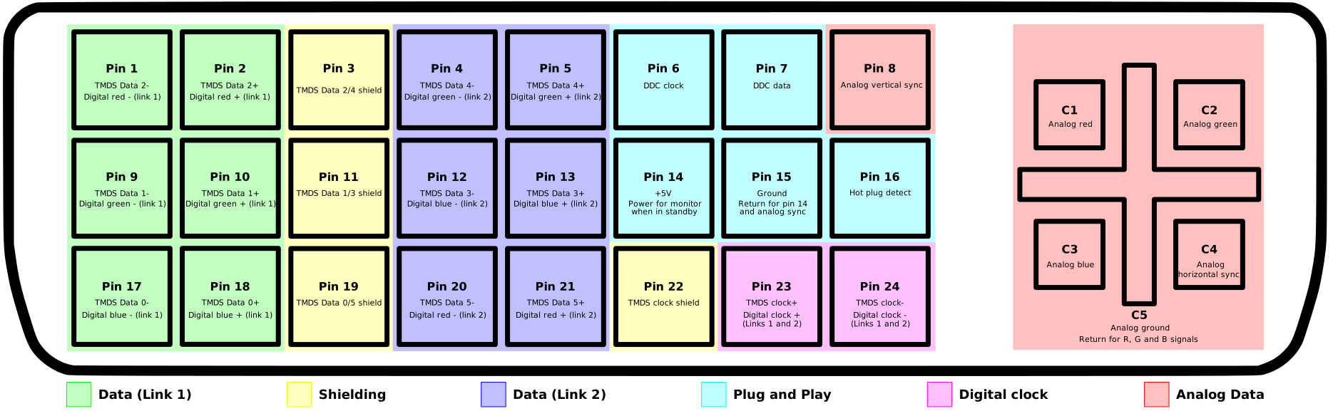
 The pinouts are quite simple to folow as ADC shares a lot in common with DVI as they are both digital. ADC Pinout and DVI Pinout.  Basically you just need to strip the dvi cable to leave just enough wire to be usable and connect the data link 1 pins, plug and play pins and digital clock pins.  The for the most part com in pairs of three (+,-,gnd)  The link 2, analog and shielding is not needed.  I also found that grounding the hot plug was required for the display port to dvi adaptor I am using to detect the monitor.  Other video cards I tested with did not need this.  The DVI spec has more information on the correct use of the hot plug pin, however I just left it grounded as the ADC spec does not include this.


The final parts needed that are not included in the DVI spec are the power and usb connections.  The monitor itself has no power supply or plug, the ADC connector needs to supply this.  I had a spare dc plug connector, so I purchased a 24v power supply off of Amazon that could supply enough amps to meet the ADC spec.  Finally there is the USB connection.  The monitor has an internal usb hub built in, also it use the USB connection to pass information about the monitor.  Unless you have the power turned on, the monitor connected and it plugged into a usb port it will not display anything!  This freaked me out at first when I started testing my solder connections and though the monitor was dead when nothing appeared with just power and the DVI connecter plugged in.


If you see weird color pixels that get better by pinching the wires together than you will need shorter leads.  It took a few tries to get the wires short enough to prevent interference.  Eventually I got it right and low and behold after connecting everything I had a clear image on the monitor.

Oddly enough right after completing this project I received a tv that can function as an external monitor so this is not as needed anymore, but I always enjoy having a few classic apple products on display.

March 13, 2011

XBox 360 Dual Firmware Mod

After months of having a 360 that works except the Samsung dvd drive, I finally bought a spare dvd drive off of ebay and decided to try and transplant the firmware from my broken driver to the new one. While I am at it, I might as well make it dual boot between the good firmware and another hacked firmware for other obvious reasons.  Now you might be asking why go through all the trouble when you can just flash the new drive.  Well my old 360 dvd drive was quite dead, to the point that I literally ripped the plcc chip off of the board with full intention of doing a complete brain transplant!  Otherwise there was no easy or cheap way to get the drive firmware key.


The above picture was all the remained of the old board, the traces where ripped up by the epoxy that was placed quite evilly on, around and under the plcc chip.  I had removed this a few months ago and has it in a safe place, waiting to have the time to use it.  Now, if you are reading this planing to do the same, I give you a big warning, if you see blank epoxy on your board, give up now.  My replacement drive had clear epoxy that was nice and soft after heating with a heat run.  However the black on the original board only got brittle making it impossible to not break parts.

Next I went online looking up everything I could find on the firmware.  On the Samung drives, It is stored on a plcc chip next to the large hole in the board. Each chip has a unique key, so you need to have this before you can use any other drives. With my drive not talking to anything, transplanting the entire chip was my last resort.  Next I found http://dwl.xbox-scene.com/tutorial/tightmod360installation.pdf it contained the steps to dual boot my old chip with the new drives one.  This way I did not need to try and remove the current plcc chip, which may destroy the board in the process.  However, it is quite a bit more work and on a whole different difficulty level.  Another warning, do not try to attempt a dual firmware setup unless you have a good soldering iron with temperature control and a very steady hand.  It is easy to get solder everywhere!


I started out with thin ethernet wire to connect the two chips. I connected all of the top lead first but quickly found it was too thick and needed to use the tiny individual strands from twisted christmas tree light wire.  Then it was easy to use long strands and connect the bottom lead first and then stretch and line it up with the top lead.  After each pair of pins where all attached correctly on a side I would trim the extra wire.


This was very delicate work, and preparing the leads was not easy, more then once I needed to carefully clean up a bridged solder connection between leads or wires.  Also it was important to completely tin each strand before trying to connect it, otherwise it would not stick.  The above picture shows how small each wire needed to be, with a penny for reference. These pictures where shown with a magnifying glass.

After that following the rest of the guide was easy, I found some spare 10K resistors and attached them to pin 4 and 15 as the guide shows.  This may differ from what others need to do, as I later needed to switch it to pin 5, as 4 caused the driver to make the 360 show a E65 error. Luckily I was persistent and kept poking otherwise I would have just assumed the drive was dead due to some error on my part.  So you may need to play with pins to get it to work on different drives.

After that I closed up the drive and connected it to the 360.  The drive boots up and reads disks, the old firmware reading games, and the new firmware without the correct key only shows everything as a dvd.  Next I need to get the drive key, but that is for another day.

December 19, 2010

X-TRONIC 4000 Digital Hot Air Rework & Soldering Station

A little while ago I purchased an X-TRONIC 4000 off ebay to upgrade from my simple craft soldering iron.  Now that I have use it a few times I can properly review it.  First off, after doing my initial research there are far better soldering stations you can purchase, however they will be far more expensive. I was not willing to pay $250+, so I was limited to the this and the Aoyue 906 which did not include as much and was a little more expensive. So with that in mind, for a hobbyist who is looking for something better than your cheap plug in iron, the X-TRONIC 4000 is not a bad choice.  It also includes a very good warranty, and while still being manufactured in China at least it is held up to some level of ISO standards and is sold by a US based company. I was able to grab one for a little over a hundred dollars, so it is not so cheap that you would expect it will break in a few uses.  Plus the included backup heating elements prolong that even further.

The hot air gun works as expected, and was pleasantly quiet.  At worst I was expecting a fish tank pump.  At high air flow, which was way too much for circuit work, you could hear the light hum.  Yet at a normal air flow settings it was rather quiet, at the lowest it was whisper quiet.  I had no problem removing a surface mount chip off an old test board with some careful blowing and medium heat.  I expect any future part removal will now be done with hot air, as it make it very simple, or possible in the case of surface mounted chips which cannot be easily removed with an iron.  I also used it to heat some epoxy for removal and that worked as well.  With the three different air tips that are included, you will be set for basic use, though it does not beat a specialty nozzle for even heating.

The hot air gun is nice, but the main feature is the iron.  After using a craft iron for even delicate work getting a serious one is amazing to use. The soldering iron heats up in about 30 seconds, which is so much faster than the three to five minutes my craft iron would take. Also using the lcd read out and the control dial, the temp is more or less kept constant.  It is important to note that the temp displayed vs what is always applied still depended on the surface area in use . The ten included tips range from tiny to very thick.  For small leads, the small tips worked well, however for a lot of normal use you will need to use a thicker tip which keeps the temp far more even.  I understand this is not so much a flaw, as it is something normal with any iron of this level and power draw.  The included stand is nothing to brag about but it does keep the iron handy and away from burnable objects.  The cleaning sponge is thin and pointless, I will be replacing it with a brass sponge eventually, until then I will stick with a damp paper towel.  In short, this will be the start of many "why did I not do this earlier" life moments.

Overall if you are looking at getting a hot air gun and nice soldering iron this should work for you.  If you do not need the hot air then there are more actuate irons you can get for the same price.

December 14, 2010

Converting an PIR outdoor light circuit for 12v

Being lazy I did not want to turn on and off my circuit tree on my desk at work, so I was just leaving it off.  However, with the Christmas season upon us, people started to bug me about not leaving it on, so I decided to get creative and convert a PIR circuit from an old outdoor motion activated spotlight to run on a safer 12v and control the tree on my desk.

First off, after eagerly prying the circuit from the lamp I quickly realizes that it did not use a transformer like I was expecting.  Most newer lights I looked at did.  So I went out looking for a datasheet on the PIR controller ic, but the one used here is either too old, or is just unlisted. This was not going to be as easy as I was expecting it to be.


This was trouble some as every PIR ic has different pinouts, and some use a first/second amp other do not.  So I went back to the basics and traced out the circuit with my multimeter and carefully sketched out the paths so I could better see what was going on.  The first thing that stood out was the four large diodes which are clearly a rectifier, to convert ac to dc.  After this, it passes through the biggest resister (blue tube) I have ever seen, which drops the voltage down to around 13v for the relay which is switched by a transistor.  From there it is dropped further to 8v and smoothed out by a capacitor for the rest of the circuit. Which is odd as an ic usually takes 5v max, but as it was unlisted I only have the trace readings to go on, so I will assume it was built to handle a larger voltage.


After figuring out this much, it was not hard to see where I would need to apply 12v to have the circuit work exactly the same but at a far safer voltage.  So after removing a small resister to break the original +120v (black) path, I now had an isolated PIR circuit and a separate circuit switched by the relay.  Right now the relay will only deal with 9v, but this leaves it open to once again control higher voltages, for potential use at Halloween.

You can see the final result below.


I am quite happy that my digital/analog circuit skills have not gotten too rusty with all the programing I tend to focus on.

November 16, 2010

Google Voice app on iPod Touch

Today I was pleased to see that Google had released an official Google Voice app, as the GVMobile+ ones from Cydia where somewhat broken.  What I was not happy with was the device not supported message that I got when trying to sync. Apparently this is only for the iPhone... Well that would not last long.  Below are the steps you need to take to get the app working on a jail broken iPod Touch.

  1. Download the ipa from the iTunes store.
  2. Change the .ipa to .zip and extract the Google Voice folder.
  3. Open and find the payload folder and grab the GoogleDialer.app
  4. Drop the GoogleDialer.app into the /Applications folder on the ipod via sftp.
  5. Respring
Interestingly enough the application works great on an iPod Touch, it just will not install via itunes.  I was looking through the ipa plist, but have not quite figured out what setting causes the restriction. Ideally removing the restriction and repacking the ipa would be best, but as I have it working, I will leave that up to someone with a bit more interest.

EDIT: Now that the official iPod version is out, this is no longer needed, unless you want the iPhone version.

October 16, 2010

Apple LaserWriter 12/640 setup with OS X

Owning an old networked Apple LaserWriter LS 12/640 is cool, especially as found I can use the waste toner I clean from another printer to fuel this one.  While the result is not amazing print quality, it works well for the occasional print job at home.  The big problem is that setting up the printer is no longer supported in OS X, yet there is some unix and window hackery that will do the trick, the problem was getting them all to work from my Macbook Pro and not having to drag a PC into the mix.

First off you need to setup an IP for the printer, which by default has an IP of 0.0.0.0 and a subnet of 0.0.0.0.  Normally back in the OS 8/9 days you would use the printer utility over appletalk.  Sadly(?) apple talk has been removed as of 10.6.  So time to delve into some unix to fix the issue.

Chapter 4 in the manual for the 12/640 covers setting of the printer for unix. Basically this breaks down into adding an entry to the host file (/etc/hosts) for the printer name and ip address of your choice for the printer.  Then get the mac address for the printer, which is listed on the configuration page it will print out each time it is turned on when in config mode, e.g. little switch on back out, not in.  Then use the following arp command in the terminal "arp    -s    printer_IP_name     printer_Ethernet_address" followed by "ping printer_IP_name".  This will create a link to the printer despite an IP address not being configured.  Use this temporary link to telnet into the printer using the IP address you chose and finish up setting final network settings using the text menu system.

Next you will need to finish setting the other printer configuration items.  However they are missing from the telnet menu.  To gain access to these additional setting, such as turning off config page printing on powerup, you need to grab a copy of the Windows Laserwriter Utility.  This can be run on a pc, through a virtual machine or by using Crossover Mac to simply run it in OS X.  I used Crossover, installed the utility and it connected automatically the first time I ran it.  You can tell the setting have been changed as the printer will be sent a job for each command and then print a wasteful page that confirms each change.  After that the printer will be all set up and ready to be added to your printer list.  The 12/640 driver is pre installed in 10.6, but must be chosen manually.

Once again I am recycling old tech for current use.  Plus it is a pice of Apple history, is your made by Apple, for most that would be a no.

August 12, 2010

Hydro Thunder Hurricane Review

For a couple of months now, I was eagerly awaiting the release of Hydro Thunder Hurricane(HTH), a ten years in the making redesign of the 1999 hit arcade racer Hydro Thunder(HT).  While there are already numerous reviews out about the game I figure I would throw in a little depth  with my 2 cents.

First off, the game carries the HT name quite well, however to fully enjoy it, you have to remember that this is not the same game we know and love.  The boats are back and the race courses are exotic with twists and turns, however gone are the crazy announcer (different less impressive announcer now), mighty hull and a few other small parts, which have been replaced by different and in some case better improvements.  The quick answer to "should I buy it" is YES, the long answer is... well read more to find out.

Controls:
The boat controls are similar to the original HT gas, boost and steer (but oddly no reverse).  However the new wave physics of the water in each course makes the actual overall feel of each race far different from the original game and takes some getting used to. Hydro jumping makes a return, but is (over) simplified down to just a button press removing what was a tricky skill related move and replacing it with something anyone can achieve by pressing x.  Might hull, the move that would smash opponents out of the way has been removed, which is a shame in single player, but makes sense in multiplayer, as it would turn into a complete mess of whoever runs out of boost first gets smashed, and there is already plenty of boat smashing going on.

Boats:
The Boats are back, minus Midway (now named Vector).  Each has two or three unlockable skins to help show off your progress and make you stand out more in races. The boats are ranked novice, pro and expert (complete with the "your crazy"). However the feel of the boats have been altered considerably.  The novice boats are not worth using after unlocking the pro boats, which may put off new players due to initial races being far more difficult to maneuver, however I urge you to keep playing because the pro/expert boat make the game far more enjoyable.  On the other hand, further in the game the expert boats that can be unlocked are way more responsive than their original counter parts, rad hazard being a good example, it is far less prone to spin out on turns, which makes it quite fun to drive now. The down side to this is that in online competition almost every player uses a expert boat, sort of making the rest of the boats pointless (design flaw).  Yet, while experienced players will probably stick with expert boats, I had no problems winning a few online multiplayer races with a Thresher(pro boat), it was just far more challenging than with the faster expert boats.  In conclusion, other than the novice boats the rest are well relatively balanced and fun to race with once you master their quirks.

Tracks:
The tracks in HTH are all new, however they carry over the feel of the classic tracks.  Below are a quick guide to the mix of each track based loosely on the classic ones.

Lake Powell (Lake Powell)
The first track, also making a triumphant return, a lot of different paths to take and a few classic shortcuts to leverage.  All in all a fun track which won't take too long to master.

Storming Asgard (Arctic Circle + Ship Graveyard)
The second track, less light and lots of ice.  A fun track with some cool surprises, though I am a little sad that the ice shortcuts require you to boost unlike the original which was crazy fast before even boosting.

Monster Island = (Jungle Adventure + Catacombs)
Third track, a circuit track with three laps that change what path is available to take due to the water level dropping.  A few too many sharp turns for my tastes, but after getting used to it it is not too bad.

Hydro Dome (Hydro Speedway)
Fourth track, a circuit track with three laps which is very fun and built for speed.  Close quarters so online play will knock you around a lot, however once you figure out the layout and shortcuts it is full throttle all the way to the finish.  I destroy with Rad Hazard on this track!

Lost Babylon (Nile Adventure)
Fifth track, this one takes a lot of play to get used to, but is probably my favorite.  Impressive visuals, lots of tricky shortcuts and quick turns make it very changeling but worth it.

Paris Sewers (New York Disaster)
Sixth track,  a circuit track with three laps, built for speed and turns, not too much else going on, but still a solid track.

Seoul Stream (The Far East)
Seventh track, night track with lots of fancy lighted waterfalls and fountains. After the initial oohs and awes, not much going for this track beyond a few interesting but hard to activate/use water powered shortcuts.

Area 51 (Greek Isles + Ship Graveyard)
The eight and last track, a lot of people love this track, I like it but it is not my favorite. Includes a lot of interesting events going on in the background to keep you entertained. Otherwise a balanced track with emphasis on speed in the later half.  Listen closely to what is said in the background during the race to get a few laughs.

Unlike the original HT, the track design in HTH are about the same in difficulty. Yep, sadly no Venice Canals successor to challenge our reflexes. Instead the difficulty of each track is controlled by what class of boat you use. Racing with a novice vs pro vs expert causes the other boats to adjust speed, use boost and take shortcuts. The expert racing is, as expected, the hardest as other boats are always at top speed.  I prefer the pro races over all.

Secrets:
Secrets on each track are back, this time in abundance, with most tracks offering several routes to choose from, ranching from normal to secrets that have to be landed in from a high drop. This is fine, however I have a minor complaint with how a lot of the secrets are set up.  A few have the classic feel, and if not taken only slow you down, however a lot of the extra paths are pointless to take. While even worse some important ones do not provide enough of a boost aid even after being extremely hard to access.  Namely, that in the original HT taking shortcuts would normal fill your boost quit well, most in HTH do not, or even waste boost to access.  This is not ruin the overall play experience, but you will occasional find your self thinking, "why did I even take this shortcut?"

Online Play:
Of all the features in HTH the one that I was looking forward to most is the online play.  Races pit you against 1-7 other players with the host of each game choosing what map is played.  I must say that the developers could have taken a cue from the Halo series and added a count down to each lobby, as I am always kicking out people who sit in a not ready state for over 20 seconds while every other player is ready to go.  Beyond that the races are as expected, far different and more challenging than with humans vs the game AI.  You tend to get knocked around far more as experienced players try to prevent others from getting boosts and accessing shortcuts.  To make things more even in races, boost is adjusted based on position, so first gets normal while 8th place gets 8X as much ofter filling the gauge, this is both annoying if you are in first and very helpful when your boat explodes from a small mistake, so I am listing it as a moot point, though in the end it does not do much to help new players win, and would have been nice to be able to disable. In the end a ranking system would have been more fair for new players; I hit the game running, but new younger players must be feeling some frustration being constantly pitted against veteran players with no chance of winning till they get used to the track and unlock better boats.  I have had a few races where I am against only one person in a novice boat, I had a good 60sec lead by the end, which is just not fair for them, but an easy win for me.  Beyond the online races the leader board keeps track of your overall rank on each track, but due to some glitch problems on tracks allowing players to achieve impossible times, the leader boards are somewhat pointless, nothing like seeing 1:20 at the top where I can only get close to 2:00 on a race with an expert boat.

Down loadable content:
While rumors are flying, it is mostly confirmed that two more tracks should be available at some point.

That about covers the game, so if you like what you have seen go buy the game, if anything go grab the demo and check it out, however be ready for the novice boats to be very lame to drive.

July 30, 2010

Install Microsoft SDK in Visual C++ 6

A recent project required me to work with the JobObject feature of the Microsoft API, this worked fine with VC++9 however when it came time to re-try it in VC++6, I quickly became aware of the fact that the base SDK that comes with VC++6 did not have a definition for the JOBOBJECT_EXTENDED_LIMIT_INFORMATION struct or the enum needed to attach it to a precess in order use it.  Sadly I needed this for a "kill at end of job command", where as other more basic JobObject features did work with the base SDK. So while I could re implement the struct I was stuck beyond that.  Lucky a SDK update fixed the issue.  But like so many other things getting the update working was not quite that easy.

VC++6 will only work with Windows Server 2003 SP1 SDK as the latest update, be careful not to grab anything newer than that. Get it Here (bottom of page) Next let it install, which will take a good ten minutes.  After it has installed then launch VC++6 and go to Tools > Options and click the Directory tab.  Now in each of the correct lists (drop down option) add an entry for either the include, bin or lib folders that are located in C:\Program Files\Microsoft Platform SDK\. Finally, the last important step is to move the new SDK items up to the top of each of these lists, if you do not the order will cause issues and the SDK files will not be used or will have errors.

Now JobObjects work as expected.

June 27, 2010

Adding an AUX to a Clarion PF-2597A-B

Originally I had planned to just buy a new after market head unit for my car, do to its lack of an AXU input for my iPod, however after seeing nothing within my price range that was decent looking, I realized that I may have been on the wrong track.  While doing some research, I stumbled upon this forum posting about adding an AUX input to an old car tape deck.  After digging some more on this topic I found that people have been successful with hijacking both the AM/FM and CD input on stereo circuits.  The CD methods seemed like a bad idea due to needing a silent cd to play constantly, which is just asking to wear out the stereo cd drive.  So I went with hijacking the FM audio out pins of the stereo.  The interesting part about using the AM/FM method is that due to the Auto Gain Control built in, when a MP3 player is connected, its stronger signal seems to overrides the AM/FM on the board and effectively shuts it off without any extra effort on your part. From what I have read, this seems to be the case with most car stereos, however your results may vary.

Here is a good place for the standard warning:  I did this project knowing it could potentially destroy the stereo and/or the mp3 player, if you attempt the same thing or something similar you face the same risks.  Do not blame me if you break anything by following my information or pictures, I express no warrantee on this information's correctness or usability.

I started off my taking the stereo apart and looking up the chips on the reverse side of the board shown here.  There is a lot of mixed opinion on where the best place to connect to is, and it seems to vary from different stereos, so it is best to see what you are working with first. While this gave me some good extra info, I quickly realized that this was not necessary, due to the pinout being printed on the back of the board.  I did some voltage checks while the stereo was plugged in and running, the FM outs gave a normal voltage variation between 0v and 3.6v, which means that I would not overload anything with a mp3 player's small voltage output. After figuring out on paper what I wanted to do and finishing my voltage checks, I did a quick test run with a temporary 1/8 inch plug connected and an older expendable mp3 player.  While I was expecting this to work out, it was exciting to hear it function, when the player was plugged in, the FM cut out and the mp3 was clearly playing unplug it and the FM comes back as normal.  While the signal is stronger, the max voltage from the mp3 player is lower than the FM, so the mp3 player needs to be set to at least half volume to be heard well, not bad, but definitely not perfect.  There may be a better connect point that uses a lesser voltage, however I am sticking to the ones on the edge due to it being easy to access and solder.

After testing and finding out that this did indeed work, I drilled a hole in the back of the stereo and added a 1/8 inch plug and then ran a short shielded audio cable to the pins I used in my test.  The board picture above has the final wiring, which pokes out of the side and is soldered to the correct pins coming from the separate AM/FM board and ground which is a larger solder point connecting to the metal housing.  By using a shielded cable inside the radio, it will prevent any extra interference due to the wire stretching across the board from the back panel. After doing one final check, I reassembled the stereo, now with its new AUX plug.  Finally, I put together a separate cable to plug into this AUX port and run it to a more convent location in the center console.

The wire runs down from the back of the stereo and connects to another 1/8 inch plug from which I can easily plug in an mp3 player or another other audio device. After making sure everything was in order I snapped all the console panels back into place leaving just the new 1/8 inch port left in view.  This is nice, because it means that there is no obvious indication that the stereo is no longer stock, making it a far less likely target for theft, not that the radio is easy to get out to begin with.

After doing some actual road testing and letting it run for a while using my expendable mp3 player, I am quite satisfied as well as confident that there is no chance it will harm my iPod, so now I am ready for the commute on monday morning.  I must say that the only down side to this setup is that the mp3 volume needs to be over 50% and the stereo volume ends up being about 12 higher than cd or radio (25-30 vs 10-15 out of 40).  Not that this is a problem, it is just the only flaw to the design and may be fixed by using a closer point to the volume control chip.  Either way, I am happy and my car now has a handy AUX port, all at the cost of $3 for 1/8 inch plugs.

Other possible options instead of this and costs...
DIY AUX ($0-$50 depending on your extra parts supply)
Clarion CeNET adaptor EA1251B ($99 and cannot have CD Changer option installed)
New separate head unit with AUX ($60-$500)

May 15, 2010

Reading plist files

When developing for the mac platform, app preferences are supposed to be stored in ~/Library/Preferences/.  While finding and reading a preference file is easy enough, reading usable information from it is another matter.  This is because in the last couple of system updates (10.5+) the xml based plist files used for preferences are now saved in a binary format, not the UTF-8 format you would suspect.  The tricky part of this is that if you are using the NSDictonary class in Objective-C you will not encounter any problems, but when using any other programing language you suddenly get a mess of garbage text.  Luckily OSX had a built in command to help remedy the issue.  The plutil command converts plists between the text based XML and binary based.

As an example in Java you can use the Runtime class to invoke the command on the fly.

Runtime.getRuntime().exec(new String[]{plutil", "-convert", "xml1", filepath});

To convert a file back once you have read or edited it use this.
Runtime.getRuntime().exec(new String[]{plutil", "-convert", "binary1", filepath});

It is also good check for the lastIndexOf("bplist") as it will alert you if the file is currently in binary form.

April 23, 2010

Powering an Xbox 360 dvd drive

While I was waiting to be able to power my experimental/half working xbox 360 I decided to see if I could easily get the firmware keys off the drive (Note: this not for piracy, the dvd drive is not working and I would like to replace it at some point.) First off, the dvd drive is a sata drive, however it does not run off of a sata power connector, instead it has a 12 pin connector where 10 of the pins are used. Pins 1-2 are not used on the connector, pins 3-4 & 6 are +3.3v, pins 5,7,9,11 are ground, pin 8 is +5v and finally pins 10 & 12 are +12v. I was able to figure out this pinout using the post here.


Sadly, I was not able to get the key off the drive this time, however I was able to create a simple xbox 360 dvd power adaptor which was powered by a standard computer power supply, or in my case a power adaptor for powering a single computer drive. In the picture you can see my simple power supply on a breadboard, most of this is straight forward, the only tricky part is you need a 3.3v regulator to drop the +5v line down to the 3.3v the drive needs. You can see the regulator at the top of the board with two capacitors keeping the output clean at a stable +3.3v.  I did not use a switch to eject the drive, because from what I can tell, the drive motor controller is damaged and will only make a minor movement before freezing and not responding again.

While an interesting side project, it was somewhat pointless as now I can just use the 360 to power it. However it was convent to move this smaller adaptor vs a whole opened 360. Eventually I will take another stab at getting the key off, but not till I have had my fill of xbl arcade.

April 20, 2010

XBox 360 Cooling Experiments


I have an older xbox 360 that a friend had given me a while ago, it had no power brick, controller or av, and I was told that the DVD drive was not working.  As I have limited expendable money right now, it sat in storage for a few months waiting for a time where I had extra money or a reason to get it up and running again.  However, with the upcoming summer release of Hydro Thunder Hurricane I decided it would be worth finally getting the 360 ready.


I was able to snag a used power brick off bay for around $10 with shipping, so all that was left was to check out the guts while I was waiting for snail mail to arrive. First off I quickly released why the GPU overheats in 360's, the DVD drive sits on top of it, and the front has no air vents what so ever to let in fresh air.  Second the fans in the back have a single shroud instead of separate channels for the CPS and GPU, so most of the air is just pulled from just the larger CPU heat sink. I remedied this by building a wall to separate the shroud into two separate paths, forcing the right side fan to pull as much air as possible from the GPS heat sink.  Next, I add a third fan as an air intake, this was placed over the open area inside the case in front of the CPU heat sink.  I also added a plastic wall the cuts the fan air intake into two parts, half is blown into the CPU heat sink, while the other half is blown under the DVD drive so fresh cool air is available to the GPU intake. It was easy to mount a fan that fits the space, as the thin metal shield cover for the 360 has holes already drilled in an attempt to allow a pitiful amount of air to be drawn in, the holes will fit two normal sized fan screws and holds it nicely against the top of the side wall.  I removed the extra metal around the fan intake and then drilled a same sized hole into the white plastic cover above this.  Screen mesh was added to cover the fan intake and protect it. Finally, I used metal heating duct foil tape to cover the fan sides as well as do some plugging of gaps in the heat sink shroud connections.
I have never owned a 360 before, so I will have to do some heat comparisons, but it does not feel like an excessive amount of heat is being blown out the back, so I am assuming this does work to cool the insides better, or at least that is the standard thinking as I have seen that many other people have added an intake fan in this location.

March 29, 2010

DIY Fog Chiller

I have owned a fog machine for many years now, but I had always wanted to make a fog chiller to get a crawling fog effect. However, due to the wind around my house in the fall, it makes it usually pointless for halloween, so until now I had held off on spending any money on it. But when low lying fog was needed for a youth play I was helping setup and run lighting for, I finally had the excuse I needed.

So before any details, a bit of physics… A simple fog machine works by vaporizing a fluid (usually made of mineral oil, glycol, or glycol and water mixture) into a heat exchanger, where the fluid is quickly vaporized. This means that fog is usually somewhat warm, as it does cool down quickly as it expands, similar to compressed air. However it is still warm enough that it always rises as it is released. To remedy this, a fog chiller is used to cool down the fog faster so it lays low and clings to the ground. Some simple examples can be found on youtube that use a metal pipe or plate and ice to cool down the fog, which to my surprise does not need a lot of ice to achieve the task. Though watching expensive professional fog machines run is rather impressive. [Check it out]


Still I wanted to do something more than a simple metal tube, so after purchasing the cheapest plastic bin I could find ($5) I gathered up some PVC tube, mesh window screen, a 120mm computer fan and a plastic sandwich bag.

As you can see from my pictures the mesh is bent and woven into a wave shape for a clear path the smoke can move through, this ensures maximum exposure to the ice is possible and allows the fog to fill the container. Next the mesh smoke path is placed between the PVC inlet and the outlet fan using the lip in the container to to hold it up. Ice is filled all around the mesh as well as in between the gaps between the smoke path. A variable voltage transformer and a remote controlled outlet is used to control power and the speed of the fan. It is pointless to leave the fan running all the time as it will melt the ice faster. Finally a plastic bag with a stiff edge is used as a simple laminar to help smooth and direct the fog to the ground for a gentle rolling effect. While I did not get a chance to take a video of it in action I have included a video of another person's fog chiller which produced the same effect. (AKA, It is not my home, and I do not own such a sketchy rug...)


I was quite happy with the results, the ice lasted and with plenty to spare, while sitting in-between uses for a good hour. And produced a good layer of fog for the two scenes that needed it. Interestingly enough a chiller seems to works better in cold air than warm, due to it keeping the fog cool longer, which is the opposite of what I assumed, as I thought it would be better to have warm ambient air to keep the fog as the cooler sinking air. Also the slower the fog is, the lower it will stay, so if you have a container to pump it into first before cooling it will help slow it, but I will save that for the v2. As you can see from my results, if you own or want a standard fog machine (quite cheap now a-days) you need to make a fog chiller, also don't buy a combined model as they only produce a slow steady output of fog, which is only is useful for an small indoor room.